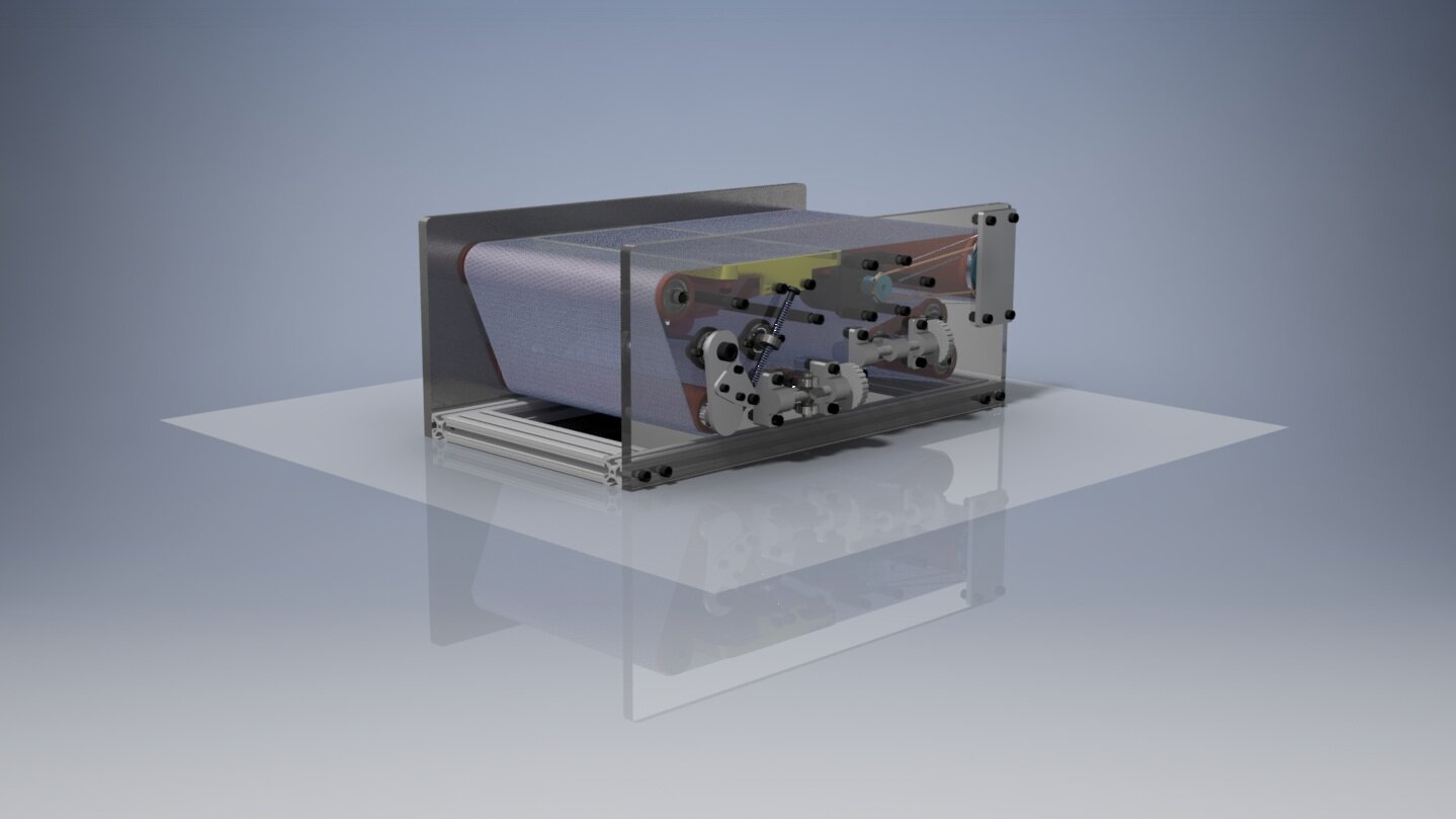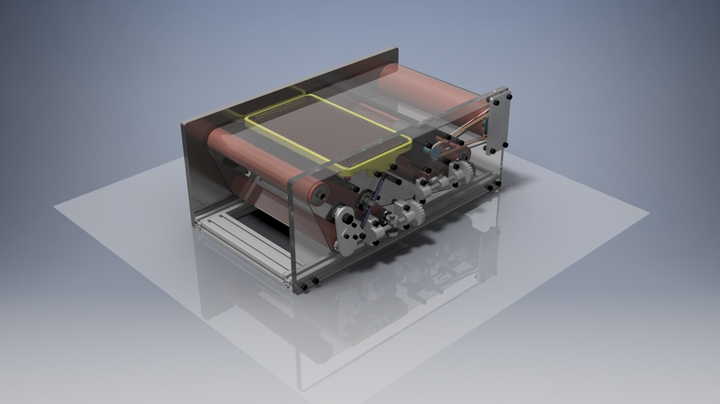
Senior Capstone: Armstrong International Wiremat Machine
For the duration of my senior year I collaborated with a 4-person team composed of my peers, working to manufacture a scaled-down model of one of Armstrong International’s manufacturing machines. Our primary goal was to copy the kinematic motion of the machine in order to provide a reliable analogue to analyze the motion of the belt running through the machine.
I had the opportunity to produce the full CAD assembly for the project, as well as work with Villanova’s machine shop to ensure all parts were fabricated on time and to specification. All components present in the assembly were modeled myself.
Duration: 1 year (2019-2020 Academic Year)
Overall Components: 218
Unique Components: 56
Softwares Used: Autodesk Inventor 2017, Solidworks 2018


Our client, Armstrong International, was in need of a scaled down model of this section of their ceiling tile manufacturing line for training purposes. This section transports wet tiles and partially dries them as they travel across it. This model will enable the client to familiarize new hires with not only the overall machine process, but also the specific effects that modifying various roller positions can have on the motion of the belt running through the machine.
While this model is certainly greatly scaled down and simplified from the original machine, it still needed to perform the same. So regardless of the original machine being roughly 50 feet wide and 100 feet long, our 2-foot by 1-foot model must have the same motion of the rollers that carry the belt. These rollers can be broken down to five main types: Stationary, Drive, Takeup, Tensioning, And Positioning.

Stationary Rollers
These rollers are the simplest and require no major modifications. Marked in the diagram above, these rollers must rotate, but have no need to change their relative location within the machine. They are driven passively via the belt running over them, and effectively act solely as supports for the belt to run across.

Drive Roller
In order to ensure the machine has sufficiently fast, powerful, and consistent belt motion, I opted to include an internally located motor that would impart rotational motion to the drive roller via a small friction-drive belt. This design relies on both the motor spindle and the drive roller itself utilize 3D printed hubs for the friction-driven belt to ride within.


So that the entire drive assembly may be internal to the machine, the drive motor will be mounted to standoffs, giving the spindle clearance between the motor and the left main plate. To ensure a proper clearance for the drive belt, a recessed path will be cut into the inner side of the left main plate. This design does come at the cost of needing a somewhat odd mounting method for the left side of the roller. In order to compensate for the slight extra width of the drive roller and the 3D printed hub’s added thickness, the left side of the roller will actually be mounted to a secondary aluminum plate - the clearance plate.

This additional plate solves the clearance problem quite simply, requiring very little additional manufacturing work, time, or money, while still maintaining the structural integrity of the area.

Here, an end-on view provides a better insight into the necessity of this clearance plate. Without this, the overall frame would have to be widened, and the mounting points for every other roller would have to be changed, as the other rollers have a lesser width than the drive roller.

Takeup Roller
The takeup roller is perhaps the most straightforward of the specialized rollers, as it is only required to move in a linear manner, co-linear to the direction of travel of the belt. This roller’s motion acts to effectively modify the overall distance that the belt covers in a single rotation. In doing so, gross control of the belt path is achieved, which is then further adjusted by the tensioning roller. Both of these together facilitate fine control.

Tensioning Roller
In order to minimize droop in the belt and ensure proper friction between the belt and rollers, a tensioning roller is necessary. The tensioning roller on the original machine functions effectively as a roller on the end of an arm that pivots in an arcing motion, controlled by a pneumatic piston. Due to size and complexity concerns, an alternative tensioner was needed. This led to the design seen above, utilizing springs pushing the pivoting arm instead, which is far simpler while still being functionally analogous for our scale. This was certainly my favorite roller configuration to design, as it required a clean but functional solution, despite the relative complexity of the system.
